

Building a Colorful “Follow Light” with Arduino
Building a Colorful “Follow Light” with Arduino
Are you tired of walking through a dull, boring corridor every day? Well, we were too. That’s why a group of us came up with an exciting idea to add some color and life into our workplace. We decided to create a “Follow Light” using Arduino, where the LEDs would light up as you walked through the corridor, creating a fun and interactive experience.
Planning and Components
To start our project, we brainstormed and wrote down a concept paper to outline our goals and requirements. We needed a controller, LED strips, and a sensor to detect movement. After considering various hardware options, we settled on using an Arduino as our microcontroller. It’s a well-known platform that is both reliable and versatile.
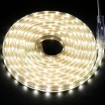
A suggestion for you to get more necessary and deeper information, please click here best outdoor led strip lights
For the LED light strips, we opted for two 5m “WS2812b-like” light strips with 300 LEDs each. These addressable LEDs allowed us to control individual LEDs, and we needed a long strip to cover the entire corridor.
However, powering such a large number of LEDs proved to be a challenge. With each LED consuming approximately 0.06 Ampere, lighting all LEDs in bright white would require a staggering 36 Ampere. We realized that the Arduino alone wouldn’t be able to deliver enough power, so we incorporated an extra power supply (5V10A) into our setup.
To detect movement, we explored different sensor options, considering factors such as the sensor’s Field of View (FOV) and range. Eventually, we settled on using a LiDAR sensor, which offered a good range, easy setup, and was cost-effective for our needs.
A suggestion for you to get more necessary and deeper information, please click here best waterproof led strip lights
Hardware and Prototype
After finalizing our components, we purchased the necessary hardware, including an Arduino UNO R3, SK6812 IC LED Strips, a Benewake TFmini Plus LiDAR, and the power supply. With our hardware in hand, we began exploring and experimenting.
We installed the Arduino CLI alongside the Arduino IDE, enabling us to compile and upload our code from the command line. Before assembling everything, we familiarized ourselves with each component and how to make them work independently.
A suggestion for you to get more necessary and deeper information, please click here outdoor rgb lights
We learned several important tips and tricks:
- Connecting the Arduino ground (GND) to the LED power supply is essential.
- Adding a resistor of 300 to 500 Ohm between the Arduino pin and the LED data pin protects the LED from receiving too much power.
- Including a capacitor of 1000 microfarads supports the power supply of the LED strip.
- Using a DC Power Connector with screws simplifies connecting the light strip wires to the power supply without requiring soldering.
Once we had each component working individually, we moved on to assembling the prototype. We created a logical flow where the LiDAR sensor provided distance data in centimeters, which we then converted into an LED pixel position. With 300 LEDs spread over 500 cm, we rounded the conversion to an integer value.
The Follow Light Prototype
With our prototype finally complete, we witnessed the mesmerizing effect of the “Follow Light” in action. As someone walked through the corridor, the LEDs would light up, following their movement. We even created a GIF to showcase our prototype in action.
What’s Next?
While our prototype is an exciting start, we’re not done yet. In the next part of our series, we’ll focus on creating a smooth animation, incorporating multiple LED strips, and installing the “Follow Light” in our corridor. Stay tuned for Part 2!


All States
Alabama
Alaska
Arizona
Arkansas
California
Colorado
Connecticut
DC
Delaware
Florida
Georgia
Hawaii
Idaho
Illinois
Indiana
Iowa
Kansas
Kentucky
Louisiana
Maine
Maryland
Massachusetts
Michigan
Minnesota
Mississippi
Missouri
Montana
Nebraska
Nevada
New Hampshire
New Jersey
New Mexico
New York
North Carolina
North Dakota
Ohio
Oklahoma
Oregon
Pennsylvania
Rhode Island
South Carolina
South Dakota
Tennessee
Texas
Utah
Vermont
Virginia
Washington
West Virginia
Wisconsin
Wyoming
Answers
(0)POST YOUR ANSWER